|
|
| 3D coordinate system | Camera looking at 3D scene |
JOGL is the OpenGL binding for Java
(JSR-231),
mapping functions as
closely as possible from C.
OpenGL is a standardized API used to draw
3D graphics to the screen (similar to DirectX / Direct3D).
The primary difference to 2D is that you need to think about z
coordinates and the
position of the viewer ("camera", including viewing angle and such).
I am writing this JOGL tutorial because I did not find another good one. The JOGL homepage is poor in information, the few tutorials are mostly outdated (not using newer functions, e.g. for textures or fonts), and the famous NeHe OpenGL tutorials are for pure OpenGL under C (Java port available though). The best API doc I found is the Python OpenGL API (better than the JOGL javadoc).
My plan for this tutorial (which is based on my experiences while writing Breed Orbiter) is:
If you like, follow me on this way...
First, a few words on how OpenGL works: Procedural. You start a
thread that repeatedly calls a display()
method at your fps (frames per second) rate; in this method, you clear
the screen and rebuild the entire scene. You do this by issuing
primitive commands: Begin vertex, this is the 1st point, the 2nd point,
the 3rd, end vertex. And so on.
Of course, it gets more complicated for textures, lighting and the
like, but the bottom line is that there is one GL object which
has like 1000 glWhatever() methods
that you will call over and over again. Yes it is primitive but near to
the hardware, and this means fast and flexible.
To integrate with Java, there have to be some concessions: Namely,
the AWT component (a GLCanvas extending Component)
is integrated into the AWT event queue, and you need to implement a
listener (GLEventListener)
for lifecycle callbacks (not so procedural here, aint it).
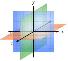
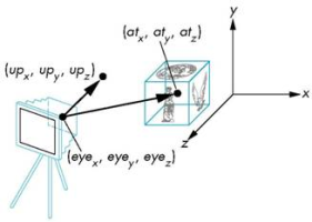
As a little prepping up for the 3D world, the figures below show coordinate system and camera.
|
|
|
| 3D coordinate system | Camera looking at 3D scene |
A positive z coordinate is coming out of the screen,
a negative into the screen. The camera position is
determined by one point to be in, another point to look at, and a
vector defining where your head is pointing into the sky (well, and a
viewing angle, but more on that later). With that, lets start doing a
bit 3D!
Before we start programming, you have to setup a bit. Other sites have described that, so I will be brief:
jogl.jar and gluegen.jar in your classpath.so, .dll) into the
library path by supplying -Djava.library.path=lib/jogl/your_path
to your java start command.And then we make a start class: Extend GLCanvas and
implement GLEventListener; and in the main method,
put the canvas into a JFrame. You will notice a constructor
and 4 event methods:
public class MyJoglCanvas extends GLCanvas implements
GLEventListener {

    public MyJoglCanvas(int width, int height, GLCapabilities
capabilities) {}

    public void init(GLAutoDrawable drawable) {}

    public void reshape(GLAutoDrawable drawable, int x,
int y, int width, int height) {}

    public void displayChanged(GLAutoDrawable drawable,
boolean modeChanged, boolean deviceChanged) {}

    public void display(GLAutoDrawable drawable) {}

}
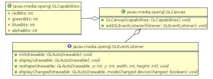
One by one, they are good for the following things:
size of the
window as well
as the minimum capabilities requirements to OpenGL.init() method is called by the AWT event queue as
soon as the window is ready; we can do some global settings here.reshape() is called
(this is important e.g. for the camera viewing angle whenever the
width/height
ratio changes).displayChanged() method. This
would be called in a multiple screen scenario.display(): This is called for every
re-rendering of the scene. It is here that we will spent most of our
time.For your convenience, the important classes so far are summarised in the following figure:
|
| JOGL starter classes (many methods omitted) |
And now, in detail. Lets start with the constructor.
    public MyJoglCanvas(int width, int height, GLCapabilities
capabilities) {

        super(capabilities);

        setSize(width, height);

    }
Seems easy enough, but where to the capabilities come from? You need
to specify them in your main method. Fortunately, this is
quite easy:
    GLCapabilities capabilities = new
GLCapabilities();

    capabilities.setRedBits(8);

    capabilities.setBlueBits(8);

    capabilities.setGreenBits(8);

    capabilities.setAlphaBits(8);
The capabilities simply define what you want from the underlying
OpenGL implementation. If the machine cannot do this, an exception will
be thrown and you know what will work and what wont. Now going to the init()
method:
public void init(GLAutoDrawable drawable) {
GL gl = drawable.getGL();
drawable.setGL(new
DebugGL(gl));
// Global settings.
gl.glEnable(GL.GL_DEPTH_TEST);
gl.glDepthFunc(GL.GL_LEQUAL);
gl.glShadeModel(GL.GL_SMOOTH);
gl.glHint(GL.GL_PERSPECTIVE_
gl.glClearColor(0f,
0f, 0f, 1f);
        // Start animator (which
should be a field).

        animator = new
FPSAnimator(this, 60);

        animator.start();

    }
A little more lines here. At first, you can notice the GL
object:
This is the one that we will issue most commands on. As a nice feature
of JOGL, we can decorate it with a DebugGL, which will supply
us with stacktraces on exceptions (as opposed to simply crashing
as it does in C).
Next, some global settings (here: my standard settings). The first
two
enable z-buffers (always needed for 3D drawing - you could also use
OpenGL to do 2D only) with last-one-wins settings (draw a rect, and a
line on it, the line will still be visible). A shade model of GL_SMOOTH
looks nice, as does the GL_NICEST correction hint. The clear
color is the CLS (ClrScr) color: Black with no translucency (alpha is 1),
specified as RGBA
in floats.
Finally, the fps thread I spoke about earlier: The animator thread
(which should be a field in our class) expects a GLCanvas and
the frame rate setting (here: 60fps). As we are in the init()
method, we can start it without fearing something is not ready in AWT.
And
now, someone could resize the window:
    public void reshape(GLAutoDrawable drawable,
int x, int y, int width, int height) {

        GL gl =
drawable.getGL();

        gl.glViewport(0, 0,
width, height);

    }
Dont ask me what exactly a view port is; it represents the part of
the screen that you can see, and we'll leave it at that (for more, wikipedia is your
friend). Ignoring the displayChanged()
method, we come to the last and most important one:
    public void display(GLAutoDrawable drawable) {

        GL gl =
drawable.getGL();


gl.glClear(GL.GL_COLOR_BUFFER_BIT | GL.GL_DEPTH_BUFFER_BIT);

    }
And now, you can start the whole thing and we can see... a black
screen (this is what glClear() does at every tick). We have
no objects yet and no camera direction, but this is something we can
change now.
For a source code view of what we have covered so far, consider looking at the MyJoglCanvasStep1.java file.
Kinda complicated just for a black screen so far, huh? I certainly think so (however I am willing to accept that this is the price of being near to the hardware). Now I want to see something! For that, we need to define our camera position in the 3D space and then actually draw something.
Consider the display() method: We will spend all our time
here. Before any drawing occurs, the camera position should be set.
This is because OpenGL is just a simple pipeline: It renders something
and promptly forgets about it, so if we change the camera position in
between, it will be confused.
For a start, we set the camera position at (0, 0, 100), which is 100
units just in front of the screen (where you are probably sitting). For
this, we need a GLU object (an OpenGL helper library with
standard geometric functions), and a setCamera() method
within display():
    public void init(GLAutoDrawable drawable) {

        glu = new GLU();

    }


    public void display(GLAutoDrawable
drawable) {

        setCamera(gl, glu, 100);

    }
And of course, the magic of setting the camera.
    private void setCamera(GL gl, GLU glu, float
distance) {

        // Change to projection
matrix.


gl.glMatrixMode(GL.GL_PROJECTION);

        gl.glLoadIdentity();


        // Perspective.

        float widthHeightRatio =
(float) getWidth() / (float) getHeight();

        glu.gluPerspective(45,
widthHeightRatio, 1, 1000);

        glu.gluLookAt(0, 0,
distance, 0, 0, 0, 0, 1, 0);


        // Change back to model view
matrix.


gl.glMatrixMode(GL.GL_MODELVIEW);

        gl.glLoadIdentity();

    }
This looks complicated, and inside, it surely is -- but this is no
concern to us. The first thing to know is that OpenGL calculates
coordinates using matrixes. For the camera, we will switch on the PROJECTION
matrix, and for everything else the MODELVIEW matrix. The glLoadIdentity()
method resets all previous matrix settings one may have made.
As for the perspective itself, that is something that GLU
takes care of. We specify a viewing angle (e.g. 45) with
respect to the current width/height ratio of the window (required by
OpenGL to calculate the actual viewing angle on screen), and a
minimum (1) and a maximum (1000) distance where we
will see things (infinity would be impossible to compute by your poor
GPU).
And then, the gluLookAt() method, which takes three 3D
coordinates:
(0, 0, distance): Where we are standing ("eye"): Here,
we modify only the z-coordinate.(0, 0, 0): Where we are looking at ("at"): Directly at
the center of the coordinate system.(0, 1, 0): Where our head points into the sky ("up"):
Directly up, along the Y coordinate (remember that Y is counted as if
on a graph, not like in an image manipulation program).And now we are out of the screen, looking in. And for what to see?
Let us go back into the display() method and add some code at
the very end:
    public void display(GLAutoDrawable drawable) {

        // Write triangle.

        gl.glColor3f(0.9f, 0.5f,
0.2f);


gl.glBegin(GL.GL_TRIANGLE_FAN);

        gl.glVertex3f(-20, -20, 0);

        gl.glVertex3f(+20, -20, 0);

        gl.glVertex3f(0, 20, 0);

        gl.glEnd();

    }
Here is it that the standard JOGL / OpenGL drawing procedure begins.
You specify a color (RGB), you say what you want (GL_TRIANGLE_FAN),
and then begin churning out coordinates. When you are finished, you glEnd()
what you started with glBegin(). And voila, our first visual
result:
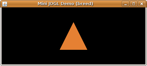
|
| Our first triangle |
You will notice that although the 3D coordinates are evenly spaced, the triangle on screen is not. This is an effect of the viewing angle: If you stand in front of a tree, you wont see its "real" height either.
And in keeping step, you might now consider looking at the MyJoglCanvasStep2.java source file.
Having a triangle is nice and all (and this is actually the basis of
almost all games out there), but how about some more sophisticated
shapes? The GLU helper library can help us again, this time
with a sphere. Again, go to the display() method and replace
the triangle section at the end:
    public void display(GLAutoDrawable drawable) {

        // Set camera.

        setCamera(gl, glu, 30);


        // Draw sphere (possible
styles: FILL, LINE, POINT).

        gl.glColor3f(0.3f, 0.5f, 1f);

        GLUquadric earth =
glu.gluNewQuadric();


glu.gluQuadricDrawStyle(earth, GLU.GLU_FILL);

        glu.gluQuadricNormals(earth,
GLU.GLU_FLAT);


glu.gluQuadricOrientation(earth, GLU.GLU_OUTSIDE);

        final float radius = 6.378f;

        final int slices = 16;

        final int stacks = 16;

        glu.gluSphere(earth, radius,
slices, stacks);

        glu.gluDeleteQuadric(earth);

    }
We set the camera to distance 30 to better coincide with the 6.378
km earth radius, then set a nice blue color (RGB = 0.3, 0.5, 1.0) and
command GLU to paint a sphere. Now, GLU uses a
concept called "quadrics", which is really just an identifier for a lot
of behind-the-scenes work: A sphere is actually drawn using a lot of
quads ("rectangle floating in space").
Everytime we want to use a GLU geometry, we have to create
one with gluNewQuadric() and, at the end, delete it with gluDeleteQuadric().
Everything in between depends on the geometry.
Above, you first see that we specify the draw style. FILL
means to fill the quads that make up the sphere's shell; it is not
the volume of the sphere. Try LINE and POINT to see
what they mean.
Next, we specify the normals. Normals are vectors that are
perpendicular to a quad, specifying where "up" is when standing on the
rectangle. This is important to OpenGL when calculating light effects
(see below). Next, the orientation of the quads is either INSIDE
or OUTSIDE; you would use the former if you wanted to paint
some kind of cave to stand in, using a sphere.
And then, the sphere itself: We call gluSphere() with the
quadric identifier, radius, and slices and stacks (think "longitude and
latitude detail along z-axis"). The result looks like the following:
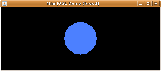 |
| Our first sphere |
The sphere looks kind of flat, but that is ok: After all, we specified only a blue color, and no lights or shadows, so where should the "3D effect" come from? Since this is not nice, we are going to change this in the next section.
For this section though, you could have a look at the MyJoglCanvasStep3.java source file.
Lighting is where the whole color model is exchanged: That's right,
throw glColor3f() away. Instead, we specify how a rectangle
surface reacts to light in its RGB spectrum (like in the real
world), and we add light sources with their own RGB spectrum (also like
in the real world).
Before we begin, let me brief you on the kind of lights. We will be
using AMBIENT and SPECULAR light, and our surface
"material" will react on this light. Ambient light is just everywhere,
with no particular source (no "3D effect" with this). We will typically
use it at strength 0.2 (of 0..1) so that we can see places dimly where
no light spot is shining. Specular light is the one coming from a spot,
and reflecting from
surfaces; this gives the typical "3D effect". I normally use it at
strength 0.8 across the spectrum.
In standard OpenGL, you can have eight light sources, but we will
be only using one. You have to specify them before drawing (remember
that OpenGL is just a stupid pipeline...), otherwise light will not be
used correctly. Once again, we go into the display() method
and set everything:
    public void display(GLAutoDrawable drawable) {

        // Prepare light parameters.

        float SHINE_ALL_DIRECTIONS =
1;

        float[] lightPos = {-30, 0,
0, SHINE_ALL_DIRECTIONS};

        float[] lightColorAmbient =
{0.2f, 0.2f, 0.2f, 1f};

        float[] lightColorSpecular =
{0.8f, 0.8f, 0.8f, 1f};


        // Set light parameters.

        gl.glLightfv(GL.GL_LIGHT1,
GL.GL_POSITION, lightPos, 0);

        gl.glLightfv(GL.GL_LIGHT1,
GL.GL_AMBIENT, lightColorAmbient, 0);

        gl.glLightfv(GL.GL_LIGHT1,
GL.GL_SPECULAR, lightColorSpecular, 0);


        // Enable lighting in GL.

        gl.glEnable(GL.GL_LIGHT1);

        gl.glEnable(GL.GL_LIGHTING);


        // Set material properties.

        float[] rgba = {0.3f, 0.5f,
1f};

        gl.glMaterialfv(GL.GL_FRONT,
GL.GL_AMBIENT, rgba, 0);

        gl.glMaterialfv(GL.GL_FRONT,
GL.GL_SPECULAR, rgba, 0);

        gl.glMaterialf(GL.GL_FRONT,
GL.GL_SHININESS, 0.5f);


        // Draw sphere (possible
styles: FILL, LINE, POINT).

        GLUquadric earth =
glu.gluNewQuadric();

        ...

    }
You see that a lot is going on. First, we define the light
parameters: The position of our only light source: A 3D coordinate (-30,
0, 0) slightly to the left, with a fourth element set to 1. This
is necessary to shine in all directions, but if you want to know why,
ask another tutorial. Next, you state the RGBA value of AMBIENT
and SPECULAR light (here: white light, evenly distributed).
The alpha value is always 1, meaning full opacity ("no glass effect at
all").
In the next three lines, we bind these parameters to a specific
light, namely LIGHT1, by specifying the parameter to set, the
appropriate array, and an index where to start in this array (this
could be different from 0 if you use one giant array for performance
reasons). Finally, we enable LIGHT1 and, most importantly, LIGHTING
at all! From now an, everything will be lighted.
Please note that if you do not change the lighting between fps
frames, you could put everything so far into the init()
method instead of display(). This would bring a bit of
performance.
Now that we have finished writing the light sources, it is time to
specify how the material reacts to the light across the RGB spectrum:
This is what used to be "the color". We take the same blue color as
before and add an alpha of 1 (full opacity); then specify it both as
reaction to AMBIENT and to SPECULAR light (this is
not necessarily so! Try experimenting if you like).
The last thing before we start drawing our sphere is the SHININESS,
which specifies how strong the reflection on the surface is (0..100).
We set it
to 0.5 here, so it has not much effect. And then,
we draw the same sphere as before -- the result:
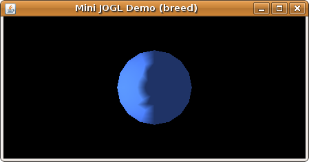 |
| A lighted sphere |
Much better, I would say! The light source from the left illuminates
the left side of the sphere with specular 0.8 light, while
the darker right side is purely made visible by the ambient 0.2
light.
As always, please follow the code by inspecting the MyJoglCanvasStep4.java source file.
We can do even better: A texture is what brings a form truly alive, by adding a pattern that our human eyes like so much. In case of planet textures, you can get a good one from Planet Pixel Emporium; the 1000x500 texture is freeware. So now, how do we apply it to our sphere?
Two steps need to be taken: First, we need to load the texture from a PNG file and assemble it into a form JOGL can understand. Second, just before drawing the sphere, we have to tell JOGL that the next thing coming should use the texture ("bind the texture to the GL context").
The first step used to be difficult with OpenGL (see
excerpt); in JOGL, we have
helper classes such as the TextureRenderer
that do most of the things for us. In the init()
method,we load the texture:
public void init(GLAutoDrawable drawable) {
// Load earth texture.
try {
InputStream stream = getClass()
TextureData data = TextureIO.newTextureData(stream, false, "png");
earthTexture = TextureIO.newTexture(data);
}
catch (IOException exc) {
exc.printStackTrace();
System.exit(1);
}
}
For this purpose, we retrieve an input stream (standard Java
IO: image must be in same package as class) and command TextureIO
to read the texture data; apart
from the stream, we specify false to supress generation of
mipmaps ("up/downscaled versions of the texture for different viewing
distances"), and supply the file ending. Then, we generate an OpenGL earthTexture
from the data, again using TextureIO.
In the display() method, we put this earthTexture
into use, by binding the texture to the GL context before proceeding
with drawing the sphere.
    public void display(GLAutoDrawable drawable) {

        // Set material properties.

        float[] rgba = {1f, 1f, 1f};

        gl.glMaterialfv(GL.GL_FRONT,
GL.GL_AMBIENT, rgba, 0);

        gl.glMaterialfv(GL.GL_FRONT,
GL.GL_SPECULAR, rgba, 0);

        gl.glMaterialf(GL.GL_FRONT,
GL.GL_SHININESS, 0.5f);


        // Apply texture.

        earthTexture.enable();

        earthTexture.bind();


        // Draw sphere.

        GLUquadric earth =
glu.gluNewQuadric();

        glu.gluQuadricTexture(earth,
true);

    }
Compared to the previous version, you can see three changes: First,
we change the material color to white (1f, 1f, 1f), because
now the texture shall define the color of each spot on the surface.
Then, we enable() textures globally (switch this off again if
you want an untextured surface come next), and then bind()
the specific texture for whatever comes next.
And next comes the GLU sphere! Here, we need to make only
one change: Announce that we indeed want to use the current texture for
the next form. This is kind of redundant, and GLU specific:
If you draw triangles (or quads), you wont have to do this.
The rest plays out as before, resulting in the following:
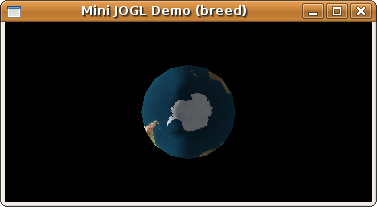 |
| A textured sphere |
And this is the earth! Seen from the south pole, and that is because
GLU always paints at 0, 0, 0 and along the z-axis; and we are
looking along the z-axis into the monitor. No worry, we can change the
zero position ("translation"), and also the alignment of the body
("rotation") -- stuff for the next chapter!
For a review of what we have done so far, have a look at the MyJoglCanvasStep5.java source file.
So now we have the basics of triangles, bodies, light and material,
and texture. In our toolkit, there is only one basic thing missing: How
to arrange the bodies we draw in the 3D space. You only need to
memorize two methods names here: glTranslate() and glRotate().
What I want to do with you is to paint a satellite on a circular
orbit around earth. This satellite will be a cube with two solar
panels. Clearly, it is unfeasible to manually calculate all those
coordinates for each point within the orbit circle. Therefore, we will
simply shift what is considered to be the zero point (0, 0, 0).
Before any drawing begins, we load a secondary texture for
the solar panel in the init() method. This also demonstrates
nicely how to use multiple textures. I used GIMP and a scanned foto to
produce a solar panel texture
with font on it.
public void init(GLAutoDrawable drawable) {
// Load the solar panel
texture.
try {
InputStream stream = getClass()
TextureData data = TextureIO.newTextureData(stream, false, "png");
solarPanelTexture = TextureIO.newTexture(data);
}
catch (IOException exc) {
exc.printStackTrace();
System.exit(2);
}
}
Having that, once again we go into the display() method,
this time computing the orbit position and drawing a satellite (silver
cylinder plus textured panel). For a start, we will cover the cylinder
at the right position.
    public void display(GLAutoDrawable drawable) {

        // Save old state.

        gl.glPushMatrix();


        // Compute satellite
position.

        satelliteAngle =
(satelliteAngle + 1f) % 360f;

        final float distance =
10.000f;

        final float x = (float)
Math.sin(Math.toRadians(satelliteAngle)) * distance;

        final float y = (float)
Math.cos(Math.toRadians(satelliteAngle)) * distance;

        final float z = 0;

        gl.glTranslatef(x, y, z);

        gl.glRotatef(satelliteAngle,
0, 0, -1);

        gl.glRotatef(45f, 0, 1, 0);


        // Set silver color, and
disable texturing.


gl.glDisable(GL.GL_TEXTURE_2D);

        float[] ambiColor = {0.3f,
0.3f, 0.3f, 1f};

        float[] specColor = {0.8f,
0.8f, 0.8f, 1f};

        gl.glMaterialfv(GL.GL_FRONT,
GL.GL_AMBIENT, ambiColor, 0);

        gl.glMaterialfv(GL.GL_FRONT,
GL.GL_SPECULAR, specColor, 0);

        gl.glMaterialf(GL.GL_FRONT,
GL.GL_SHININESS, 90f);


        // Draw satellite body.

        final float cylinderRadius =
1f;

        final float cylinderHeight =
2f;

        GLUquadric body =
glu.gluNewQuadric();

        glu.gluQuadricTexture(body,
false);


glu.gluQuadricDrawStyle(body, GLU.GLU_FILL);

        glu.gluQuadricNormals(body,
GLU.GLU_FLAT);


glu.gluQuadricOrientation(body, GLU.GLU_OUTSIDE);

        gl.glTranslatef(0, 0,
-cylinderHeight / 2);

        glu.gluDisk(body, 0,
cylinderRadius, cylinderSlices, 2);

        glu.gluCylinder(body,
cylinderRadius, cylinderRadius, cylinderHeight, slices, stacks);

        gl.glTranslatef(0, 0,
cylinderHeight);

        glu.gluDisk(body, 0,
cylinderRadius, cylinderSlices, 2);

        glu.gluDeleteQuadric(body);

        gl.glTranslatef(0, 0,
-cylinderHeight / 2);

    }
The first thing you see is glPushMatrix(). Since we will
be tinkering with the default position, a backup is useful; after we
are done drawing, we will restore it via glPopMatrix(). Next,
we compute the satellite position: A circle around the z axis, computed
with sin() und cos() from the standard Java
libraries. To track the current position, we will simply store a satelliteAngle
(0..359) which advances 1 degree with each display() call.
And then, the interesting thing happens: Using glTranslatef(),
we shift the default position to where the cylinder should be; so for
the next GL or GLU commands, their "local"
coordinate (0, 0, 0) is at our "global" (x, y, z).
You also see another position manipulation: With glRotatef(),
the local coordinate system can be rotated: First around the z axis
according to the satellite angle, then 45 degrees around the
y axis (so we have a nice isometric view on the cylinder and the
panels).
Setting the material properties for the cylinder begins with a glDisable(GL_TEXTURE_2D).
This is because the earth texture we used earlier is still in effect:
If we would draw the cylinder now, it would be earth textured. The rest
of the material properties is simple: Gray color in ambient and
specular spectrum, and a high shininess rating (90) to let the
silver reflect light properly.
The cylinder itself should look somewhat familiar: A new quadric is
created, and here it is used 3 times: 2 disks ("top and bottom of
the pipe") and a GLU cylinder (which is a pipe, not a can).
Since GLU
always works from its local (0, 0, 0), we have to glTranslatef()
along the z axis while drawing disk, cylinder, disk. Afterwards, the
last translation restores the previous state.
Since this is the last chapter, I will now load even more stuff on
your brain: We will do the solar panel texturing the "classic way". If
you ever want to texture quads or triangles by yourself (not using GLU),
you will need this. To make things simpler, we will draw only one large
solar panel, which goes straight through the cylinder.
    public void display(GLAutoDrawable drawable) {

        // Set white color, and
enable texturing.


gl.glEnable(GL.GL_TEXTURE_2D);

        gl.glMaterialfv(GL.GL_FRONT,
GL.GL_AMBIENT, rgba, 0);

        gl.glMaterialfv(GL.GL_FRONT,
GL.GL_SPECULAR, rgba, 0);

        gl.glMaterialf(GL.GL_FRONT,
GL.GL_SHININESS, 0f);


        // Draw solar panels.

        gl.glScalef(6f, 0.7f, 0.1f);

        solarPanelTexture.bind();

        gl.glBegin(GL.GL_QUADS);

        final float[] frontUL =
{-1.0f, -1.0f, 1.0f};

        final float[] frontUR =
{1.0f, -1.0f, 1.0f};

        final float[] frontLR =
{1.0f, 1.0f, 1.0f};

        final float[] frontLL =
{-1.0f, 1.0f, 1.0f};

        final float[] backUL =
{-1.0f, -1.0f, -1.0f};

        final float[] backLL =
{-1.0f, 1.0f, -1.0f};

        final float[] backLR =
{1.0f, 1.0f, -1.0f};

        final float[] backUR =
{1.0f, -1.0f, -1.0f};

        // Front Face.

        gl.glNormal3f(0.0f, 0.0f,
1.0f);

        gl.glTexCoord2f(0.0f, 0.0f);

        gl.glVertex3fv(frontUR, 0);

        gl.glTexCoord2f(1.0f, 0.0f);

        gl.glVertex3fv(frontUL, 0);

        gl.glTexCoord2f(1.0f, 1.0f);

        gl.glVertex3fv(frontLL, 0);

        gl.glTexCoord2f(0.0f, 1.0f);

        gl.glVertex3fv(frontLR, 0);

        // Back Face.

        gl.glNormal3f(0.0f, 0.0f,
-1.0f);

        gl.glTexCoord2f(0.0f, 0.0f);

        gl.glVertex3fv(backUL, 0);

        gl.glTexCoord2f(1.0f, 0.0f);

        gl.glVertex3fv(backUR, 0);

        gl.glTexCoord2f(1.0f, 1.0f);

        gl.glVertex3fv(backLR, 0);

        gl.glTexCoord2f(0.0f, 1.0f);

        gl.glVertex3fv(backLL, 0);

        gl.glEnd();


        // Restore old state.

        gl.glPopMatrix();

    }
First, we enable textures again with glEnable(GL.GL_TEXTURE_2D).
Note that we could also have used satelliteTexture.enable(),
as we did before with the earthTexture. Material properties
are set to white, with no shininess.
The plan for the next section is to draw front and back face of a
cube, both textured. Since we want a flat, long block rather than a
die, we have to distort the dimensions: And we do it with glScalef().
In the float array section, you see the definition of the cube's
corners: Upper left, upper right, lower right and lower left for both
front and back face.
We draw GL_QUADS (rectangles). Note that you have to
specify glBegin() and glEnd() only once: Every four
vertices, OpenGL assumes automatically that a new quad begins. But
we do not only specify the vertices ("corners"): For each corner of the
rectangle, we map a corner of the texture, whereby (0, 0) is
the upper left, and (1, 1) the lower right corner of the
texture.
Additionally, we specify the normal vector ("arrow pointing into the
sky") for each rectangle, using glNormal3f(). This is
required for the lighting, so OpenGL knows where and how to reflect
light. This is also the reason why the corners and their texture corner
mappings may seem counterintuitive sometimes: Depending on the normal
vector, we have to switch left/right on the texture.
And that is it! This last step was kind of long, but we are rewarded by this sight:
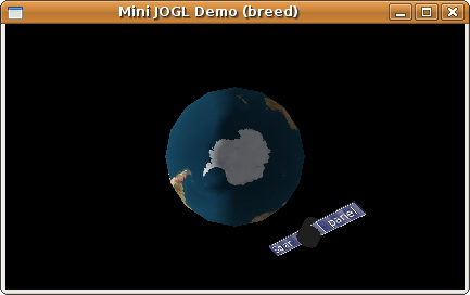 |
| A satellite in orbit |
You will note that half of the time, the solar panel is dark: This is when the sunlight strikes the back of the panel, which is reflected not into your eye, but into the screen, away from you.
And as the final source code of this tutorial, please have a look at the MyJoglCanvasStep6.java source file.
In this tutorial, we have walked through quite some JOGL functionality. We covered basic structures like triangles, quads and spheres in three dimensional space; directional lighting and material properties; and textures, which we all like so much. Finally, we worked some movement into our scene. Personally, I have worked further on the orbiter, which currently looks like this:
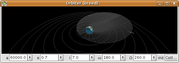 |
| Orbiter (breed) 0.2 |
And now, there is very much more to discover for you! (e.g. diffuse
lighting, translucency, or the great JOGL FontRenderer).
I hope you have been able to learn something from this tutorial;
for improvements, I appreciate all comments (preferably via mail
to kain at the above domain).
Thanks for leaving a part of your attention span here,
and have a good time!